At this point, Jay has nearly finalized the design of the hand and we’ve done as much evaluation of the rapid prototype as we can. It’s time to cut metal!
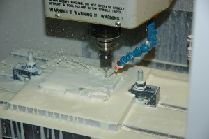
Thanks to our local Haas representative, SolidWorks has an OfficeMill OM-2A on site. The machine is perfect for this kind of project…12″x12″x8″ build envelope, small footprint, a 20-tool changer, with ten-thousandths accuracy and a 30,000 rpm spindle.
For this project, I’m using HSMWorks, one of the easiest-to-use CAM solutions available. Charles Davis at HSMWorks has been invaluable in getting me up to speed, but getting all of the tiny details right is quite a challenge. Currently, machining the parts in the hand requires 5 different end mills, 6 drill sizes, and three taps.
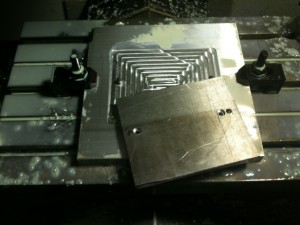
Jay designed most of the parts in halves to make my job easier. As a result, all of the parts have at least one planar surface to locate to. However, the workpiece will still need to be flipped over in order to machine the inside detail of each part. To insure the best possible alignment, I machined a base plate with two exactly-located steel pins, which fit into corresponding reamed holes on the workpiece. Because the clamps I have dwarf the actual part, I also machined holes for small button-head cap screws to hold the workpiece down during machining.
Since the locating holes were machined in-place (without subsequently breaking the setup), they should be exactly aligned to each other on the x-axis even if the plate was not perfectly squared. This means that the workpiece can be flipped end-over-end and re attached, and the second set of toolpaths should line up with the first set.
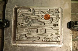
When the parts started to take shape in the mill, I suddenly realized how small they are! All of the machined parts for a finger can be milled from a single 4″x5″x1/2″ piece of aluminum. If you look closely at the picture below you can see several small holes — the smallest of these are clearance holes for the 0-80 machine screws which will hold the pairs of parts together!
Because the parts will be machined from both sides, I need to leave enough material for most of the parts so that they can be machined from above without being torn off the rest of the workpiece by the cutting forces. As a result, most of what you’re seeing in this part is actually where parts are not — the voids which will exist in the assembled pairs. The outer profiles will be cut when the parts are machined from the other side.


