Bubbles…In The Water…

We made two unorthodox decisions for this project.

First, we chose to use passive hydraulics instead of either an electric servo-driven hand or powered hydraulics/pneumatics.  This was an attempt at both simplicity and “free” force-feedback.

Second, we chose to use water as our working fluid.  We wanted something safe and as low-viscosity as possible due to the large number of small-diameter lines and fittings used in the hand.

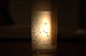
Here’s what I didn’t know about water: it has air dissolved in it, and that air will come out at the slightest drop in pressure.  Given that water in the tap is generally at around 80 psi, even bringing it to atmospheric pressure causes bubbles to dissolve out.  Likewise, in certain conditions a vacuum is created in our lines.  When this happens, force-sapping, feedback-killing air bubbles appear in the tubes.

To prevent this, I attempted using a MityVac to vacuum the air out of the water.

My thinking is that a) the vacuum from the MityVac is greater than the vacuum created in our system and b) any small air bubbles which fail to get removed by the bleeding process will dissolve back into the water, thus the system becomes “self-bleeding” for small amounts of air.

A test with the “vacuumed” water and two cylinders with short lines suggested that this technique works until large amounts of vacuum occur.  It also suggests that there may be some air leakage through the nose seal on the cylinder under vacuum conditions, but the rear circuit appears to be well sealed.

I’ll repeat the test using a “real” vacuum pump to prepare the water.
Machining Hand Parts

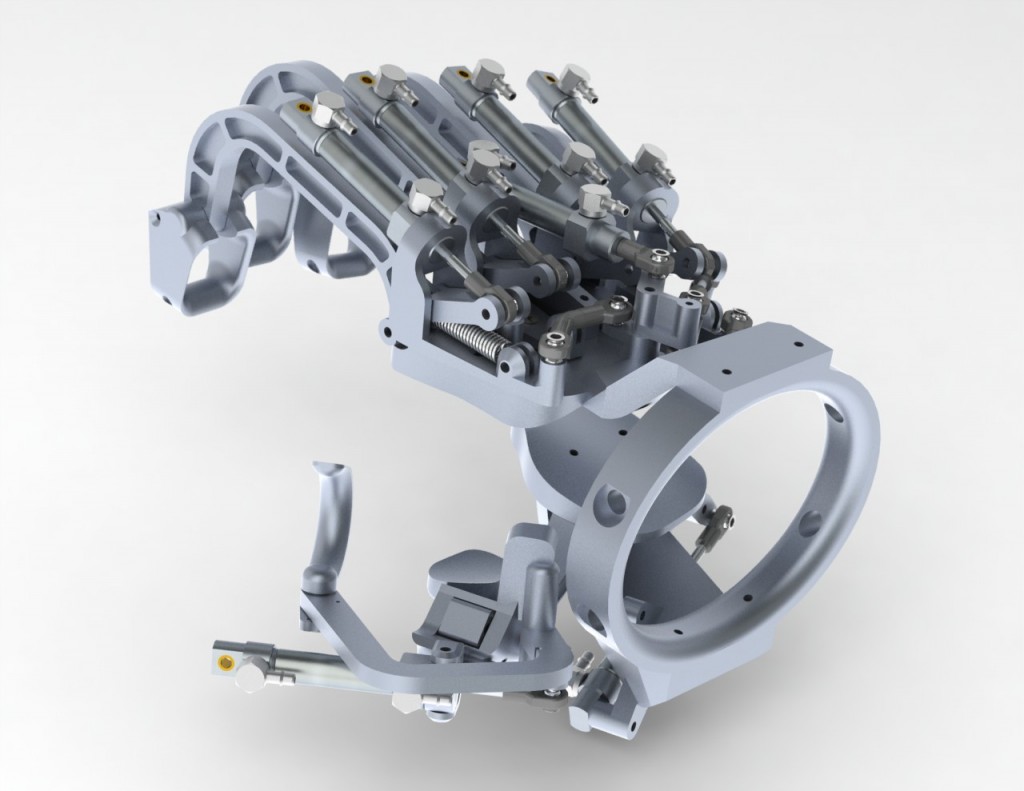
At this point, Jay has nearly finalized the design of the hand and we’ve done as much evaluation of the rapid prototype as we can.  It’s time to cut metal!

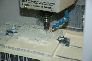
The Haas OM-2A in action...

Thanks to our local Haas representative, SolidWorks has an OfficeMill OM-2A on site.  The machine is perfect for this kind of project…12″x12″x8″ build envelope, small footprint, a 20-tool changer, with ten-thousandths accuracy and a 30,000 rpm spindle.

For this project, I’m using HSMWorks, one of the easiest-to-use CAM solutions available.  Charles Davis at HSMWorks has been invaluable in getting me up to speed, but getting all of the tiny details right is quite a challenge.  Currently, machining the parts in the hand requires 5 different end mills, 6 drill sizes, and three taps.

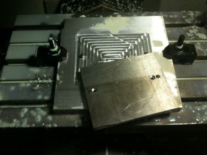
Jay designed most of the parts in halves to make my job easier.  As a result, all of the parts have at least one planar surface to locate to.  However, the workpiece will still need to be flipped over in order to machine the inside detail of each part.  To insure the best possible alignment, I machined a base plate with two exactly-located steel pins, which fit into corresponding reamed holes on the workpiece.  Because the clamps I have dwarf the actual part, I also machined holes for small button-head cap screws to hold the workpiece down during machining.

Base plate with locating pins, and unmachined workpiece

Since the locating holes were machined in-place (without subsequently breaking the setup), they should be exactly aligned to each other on the x-axis even if the plate was not perfectly squared.  This means that the workpiece can be flipped end-over-end and re attached, and the second set of toolpaths should line up with the first set.

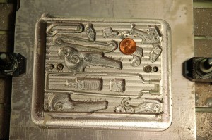
When the parts started to take shape in the mill, I suddenly realized how small they are!  All of the machined parts for a finger can be milled from a single 4″x5″x1/2″ piece of aluminum.  If you look closely at the picture below you can see several small holes — the smallest of these are clearance holes for the 0-80 machine screws which will hold the pairs of parts together!

The underside of the parts for the middle finger. Note the penny for scale.

Because the parts will be machined from both sides, I need to leave enough material for most of the parts so that they can be machined from above without being torn off the rest of the workpiece by the cutting forces.  As a result, most of what you’re seeing in this part is actually where parts are not — the voids which will exist in the assembled pairs.  The outer profiles will be cut when the parts are machined from the other side.

Tags: , ,

Obtaining an accurate human hand reference

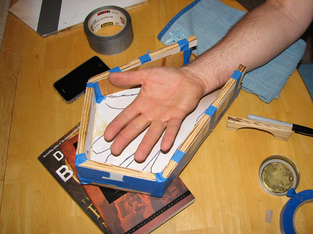
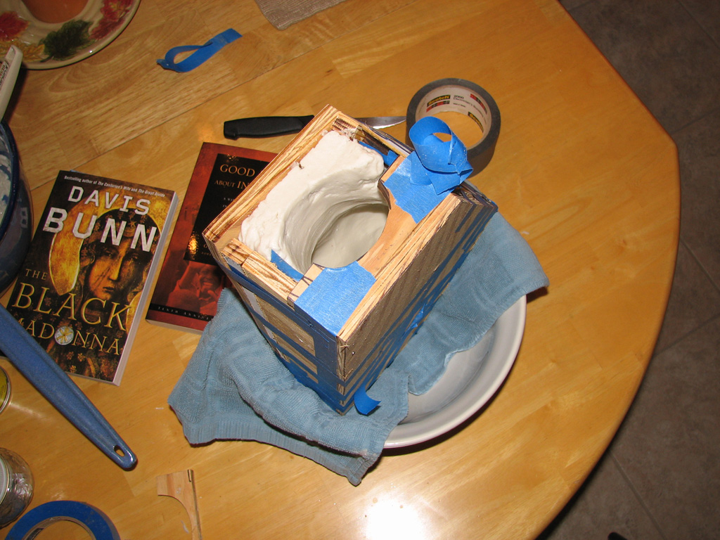
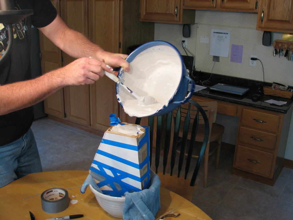
Well, after weeks of frustration using a “generic” human hand mesh, I decided the best way to go forward would be to get a scan of my right hand to model to. To do this, I spent part of a morning last week creating a cast of my hand using Alginate (Dental mold matl.) and creating a mold and then pouring plaster into it. Alginate is a great “impression” material for creating quick molds but the down side is that you need to work very quickly and it only has a mold “shelf-life” of about 3 to 4 hours.  Of course, you can only do a one-off cast. In any case, it’s perfect for what I want. You can get it a art supply stores or you can talk to your dentist to see if they would sell you some. I have a dentist friend who supplies me. This stuff sets up in a matter of a few minutes (I mean like 3 to 4 minutes max!) to slow down the set time, use ice water.

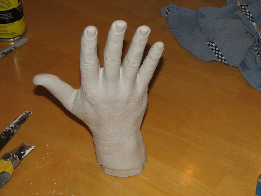
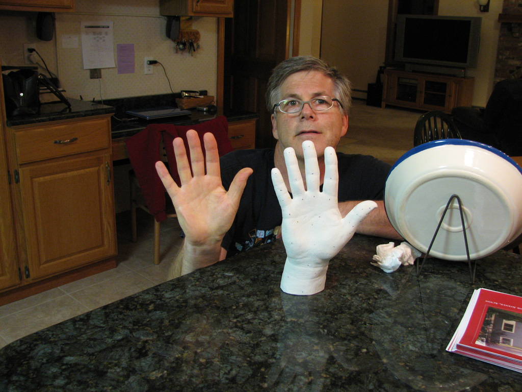
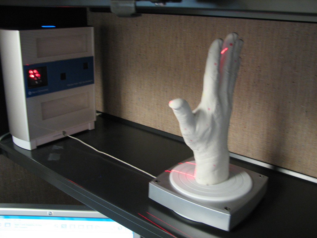
After making the mold, I quickly mixed up some Plaster-of-Paris. I poured it into the mold and let is set for about an hour. I then removed the mold box and peeled away the Alginate material. With a little cleanup to the cast using an Xacto knife to scrape and sculpt, I finally had an accurate representation of my hand to scan. Now with the cast, I create a number of black, red and blue dots on the cast called “correspondence points.” These are necessary for when it comes time in the ScanStudio Software to align the various scan passes together. I placed it on the Next Engine Scanner turntable and set it for wide mode (15 to 17 inch – shoebox size object) at quick, low-res and a 9 pass turntable scan. I also did a 3 pass bracket of the thumb. After a few more hours in ScanStudio, I cleaned up the meshes, aligned them and knitted them together. I then brought in an .scn file into SolidWorks with the image map (texture of correspondence dots) which is very useful along with the mesh to model to.

Now I have an accurate mesh to reference to in SolidWorks. Because I have the ScanTo3D add-in. I can directly reference (snap to)  the mesh when I sketch 2D or 3D entities on it.


Mold box for hand

Alginate Mold ready for plaster pour

Pouring Plaster into mold

Final cast of my right hand

A perfect copy of my right hand

Scanning Cast with Next Engine Scanner

Scanned mesh in SolidWorks

Rapid Prototyping

We have had good success with the Solido Rapid Prototyping machine. I have been able to explore a number of different concepts, all at various levels of detail, that have help me understand the fit and function around the human hand. Working out the spacing and dexterity around the joints of the hand is an extremely complex exercise. RP helps to quickly reiterate concept to figure out what works.

Peeling away excess material (support structure) from laminated block from Solido machine

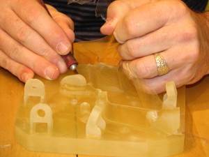
closeup of peeling away support material (no. 11 Xacto knife is your best friend)

Master Control Rig

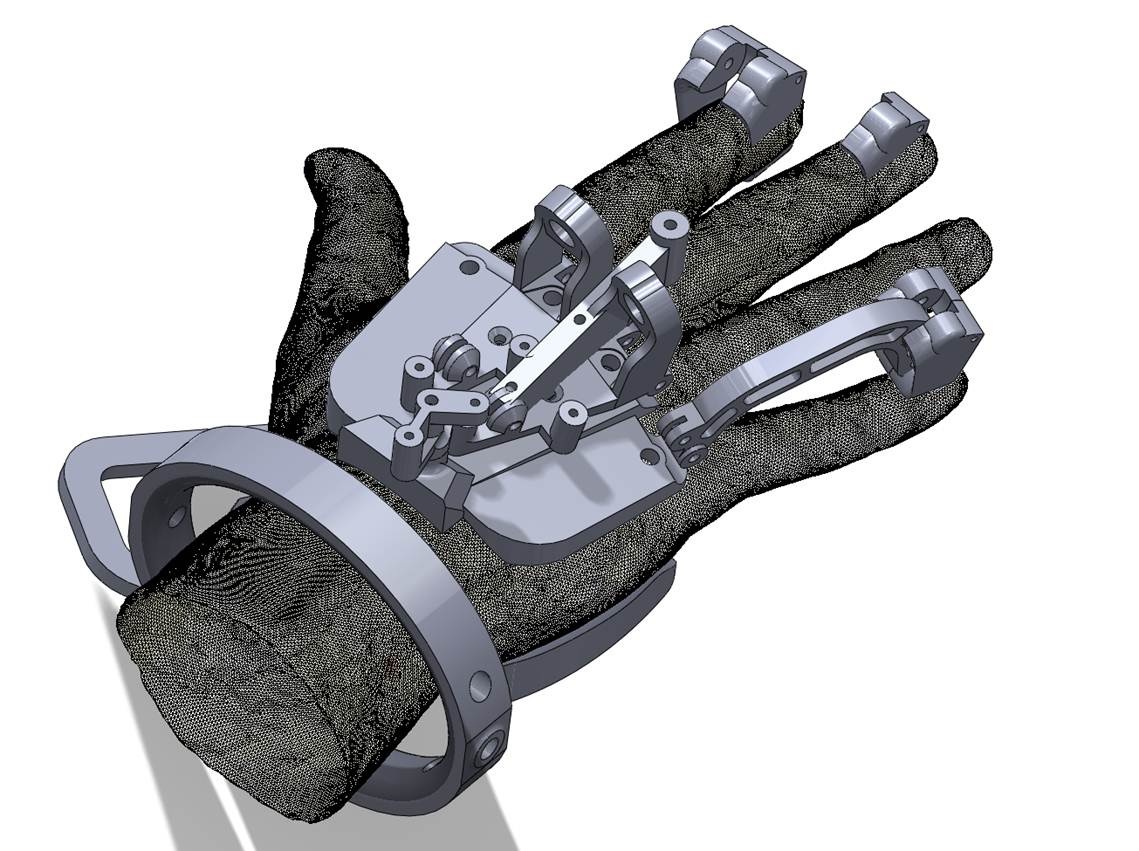
It turns out that the most difficult challenge in this project is the controller. To fit to “a” human hand, let alone a range of human hand/arm sizes, is a very difficult exercise indeed. This is were Rapid Prototyping has paid for itself. Many different concepts have been explored for “rigging” the hand to control the robot hand/arm. The most difficult area centers around the fingers and thumb.  below is an image of one of the early concepts for the control rig for the fingers and thumb.

early concept of control rig for hand (mechanism for arm not shown)

co

Forearm: Barrel Cam Rapid-Prototype

To verify the functionality of the barrel cam, a portion of the arm was rapid-prototyped.

After de-waxing, the parts were assembled and the mechanism checked by moving the cam through its range of motion.  The rotation worked as expected, although we discovered a few other issues from the model.  First, the combination of the split design (which makes capturing the bearings easier) and the thin arm sections (seen on the left side of the picture above) makes the arm less rigid than the previous cylindrical design.  Second, any deformation of the arm in the area of the cam will tend to make it bind.  In the next iteration, another thin beam will be added to attempt to stiffen this area sufficiently.

Forearm Iteration #3: Aesthetics

An aesthetic study on the current arm design.  The primary goal was to expose the mechanism, so the parts are based on the existing design but with several slots and windows cut to allow viewing of the mechanism.

Forearm Iteration #2: Barrel Cam

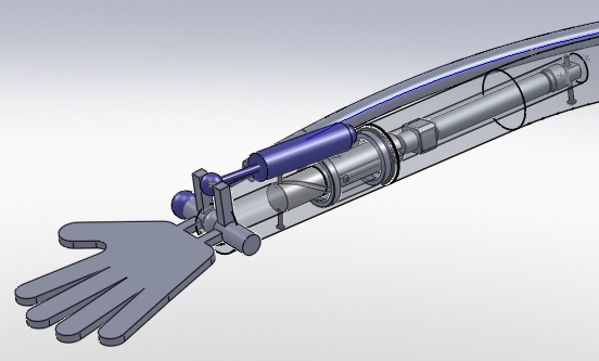
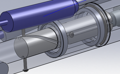
In my second iteration, I used a barrel cam with a helical groove cut into it to convert the linear motion of the hydraulic cylinder to a rotation of the forearm, which is supported on to 25mm bearings.  (Although rotary actuators were considered, they were rejected because we want to keep the basic form factor of a human arm.)

A close-up of the cam showing the modified machine screws used as followers.

Forearm Iteration #1: Mimicking Human Arm

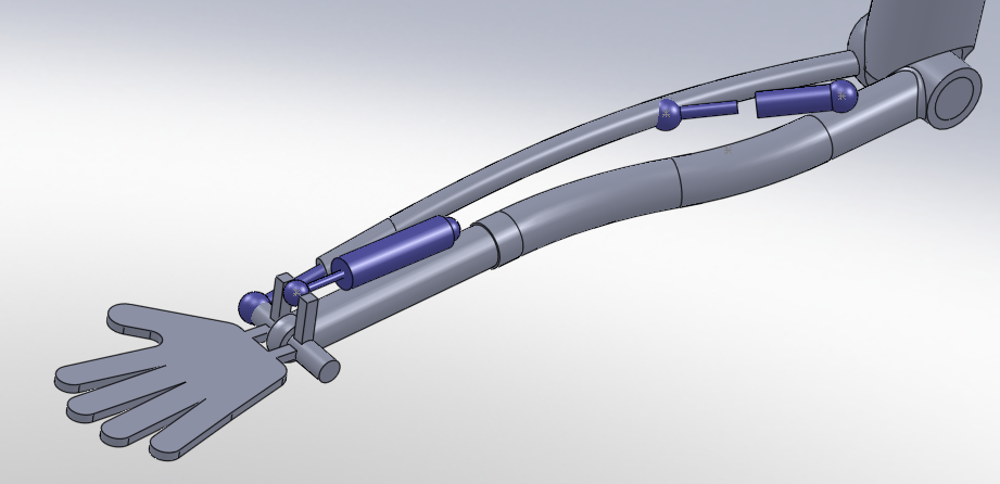
In my first iteration (above), I attempted to replicate both the skeletal and muscular features of the human arm to the greatest degree possible.  (Note that the hand itself has not yet been modeled so the part shown is simply a placeholder.)

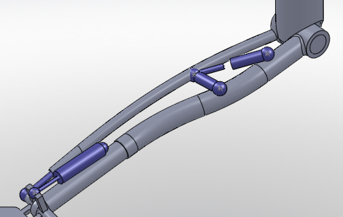
To reduce complexity, the musculature for pronation and suppination was simplified to a single air cylinder between the ulna and radius.  By driving this cylinder in both directions (i.e. double-acting), I hoped to both pronate and suppinate the arm.  However, closer inspection of the cylinder travel throughout the twisting motion revealed that at certain angles the cylinder’s leverage would be insufficient to stabilize the rotation, and furthermore its response was very non-linear, which would cause difficulty in driving it with the controller.

Although I also investigated the use of two cylinders (see above) to retain some linearity, it seemed like the design was losing its elegance and a more robust rotation driver is needed.

Research: Human Arm Mechanics

I began the arm design by researching how the human arm works, as well as various equivalent joint models which have been developed.  My plan was to replicate human physiology to the greatest extent possible.

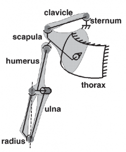
While much of the motion of the human forearm is relatively straightforward, the pronation and suppination (i.e. “twisting” inward and outward, respectively) of the forearm is surprisingly complex.  Maurel et al presented a mechanical model of the forearm joints in a 1996 paper entitled “A Biomechanical Musculoskeletal Model of Human Upper Limb for Dynamic Simulation”.  In it, they modeled the forearm joints as a combination of cylindrical and spherical joints, as shown here:

However, note that the surface to which the wrist is attached changes its orientation as the forearm is rotated, as shown here:

This means that without correction, the wrist in our arm would rotate to the left or right as the forearm was twisted.

Another challenging aspect of the forearm motion is the musculature involved.  Somewhat counter-intuitively, the two directions of twisting are driven by different, non-symmetric muscles.  As shown in this video, the muscles which pronate the forearm (pronator teres and pronator quadratus) are both contained in the forearm.  However, the muscles which suppinate the forearm (biceps brachii and suppinator muscle) are located in the upper arm and forearm respectively.